Please activate JavaScript!
Please install Adobe Flash Player, click here for download
ePaper created 2017-12-13, 11:39:59 | version 1.38.0
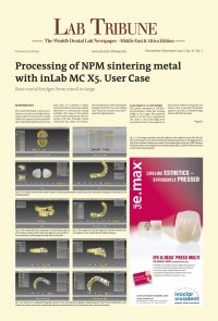
B2 ◊Page B1 LAB TRIBUNE Dental Tribune Middle East & Africa Edition | 6/2017 Fig. 11-12: At the end of the design process, the connector lines were adjusted Fig. 13: The fi nal check was performed on the preview screen, from where the data was exported to the in- Lab CAM 16.0 software. Fig. 14: In the current version of the CAM software, the inCoris CCB blank can easily be identifi ed by QR code detected by a webcam — a convenient feature that can also be used for all other inCoris blanks. The QR code provides all of the necessary information on the current blank without the inconvenience of man- ual data entry; the software even recognizes already partially milled blanks. Fig. 15: As this case shows, the restoration to be milled could be positioned within the blank quickly and without any complications Fig. 16: In the production preview, the sprue connec- tions were reduced and the milling job passed on to the laboratory’s own inLab MC X5 5-axis milling unit Fig. 17, 18: The software presents a reminder screen at this point (Fig. 17) to ensure that both the correct work- piece and the corresponding tool magazine are loaded into the unit (Fig. 18). Fig. 19: After 20 minutes of wet milling, the work- piece with the milled bridge framework is removed from the inLab MC X5. The blank was allowed to dry overnight and the framework separated the next day. Fig. 20: Since the inCoris CCB blank is made of a sintering metal, the next step was the sintering step that brought the framework to its fi nal size and strength. This step was performed in the inFire HTC speed sintering furnace (Dentsply Sirona CAD/CAM). For NPM sintering, the furnace is fi tted with an argon gas connection and a separate sintering platform. Fig. 21: After the framework, in its fi nal dimension, could now be tried on the model (Fig. 21). A tension- free fi t was noted, meaning that the framework was now ready to be veneered. Case report 2: 11-unit bridge The second case involved a much more extensive restoration. Due to the extraction of a tooth that had previously served as an abutment tooth, several bridges had to be replaced by a large 11-unit bridge. The workfl ow and approach were similar to that described for case #1. Again, the impression was taken digitally by a CEREC Bluecam and transmitted to the laboratory‘s own inLab CAD SW 16.0 unit via Sirona Connect. Fig. 22-24: The virtual design of the master model (Figs. 23 to 24) was followed by its physical production using an STL data export and a 3D printer. Fig. 25-27: For the production, the resulting job was transferred to the inLab CAM SW 16.0 (Fig. 25), where the restoration, the sprues, and the sinter support, required for the subsequent sintering process (Fig. 26) were positioned and the milling job initiated (Fig. 27).